

Next: 6. Process Management
Up: An Architecture for Parallel
Previous: 4. The DSI Kernel
Subsections
5. Memory Management
DSI's kernel provides complete memory management for processes.
In this chapter we discuss the organization of DSI's memory space
and the techniques used for distributed storage allocation and
reclamation.
5.1 Memory Organization
memory requirements are divided into three categories:
-
a large, shared heap of untyped cells;
-
a small, per-processor private data area;
-
the DSI implementation code in host executable format.
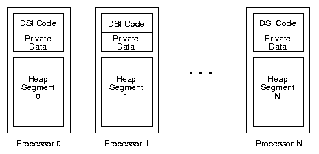
If the host architecture supports distributed shared-memory
(e.g. the BBN Butterfly),
the heap is allocated as identically-sized segments distributed
across all nodes, as shown in figure 9.
Figure 9:
DSI Memory: Physical Layout

|
These individual heap segments are mapped into the logical
address space of all processors as one large contiguous heap.
The DSI implementation code is replicated across processors
for maximum instruction locality.
If only non-NUMA shared memory is supported,
a single, large heap is allocated in shared memory,
and is artificially divided up into equal segments.
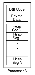
Thus, regardless of the underlying shared memory implementation,
the heap as a whole is globally shared,
and each processor is assigned responsibility for a particular
segment of the heap.
Figure 10 shows the view from one processor.
Figure 10:
DSI Memory: Logical Layout

|
5.2 Storage Allocation
DSI uses a three-level distributed storage allocation scheme.
Each level builds upon the level below it to provide its
functionality.
At the lowest level, a processor manages its own heap segment,
and only allocates from its own area.
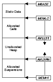
Each segment is organized as shown in figure 11.
Figure 11:
Heap Segment Organization

|
Ordinary cells are allocated in blocks from the low end of available
space ( MEMLO) upward,
while suspensions are allocated in blocks from the high end of the
segment ( MEMHI) downward.
The registers AVLLST and AVLSPN track the respective
allocation regions;
when they meet, available space is exhausted (for that node) and
garbage collection must be performed to recover space.
The reason for the bidirectional allocation has to do with garbage
collection;
its compaction algorithm is designed to relocate objects of the
same size.
This will become clearer in section 5.3;
for now, suffice it to say that if DSI had a more sophisticated
storage reclamation scheme this would not be necessary.
The second level handles the distributed aspect of allocation.
Each heap segment maintains two allocation vectors
stored in the Static Data area shown in figure 11.
The allocation vectors contain
pointers to reserved blocks of free space on other processors.
One vector is for free cell space, the other is for free suspension
space5.1.
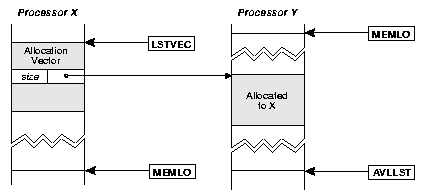
Figure 12:
Cell Allocation Vector

|
Each vector is organized as a region of contiguous unary cells,
indexed by logical processor number.
Each element's tail points to a block of free space on the
associated processor and the data field contains the size of
the block (in cells).
Figure 12 depicts a cell allocation vector.
The allocation vectors provide a general mechanism by which data
can be allocated on any particular processor in the system.
The technique of allocating larger blocks of free space and
then suballocating out of it improves efficiency by reducing
the frequency of communication costs between processors
[MRSL88].
The free blocks pointed to by the allocation vector are
preallocated and reserved;
there are no mutual exclusion problems to contend with to arbitrate
access to the blocks.
The kernel can explicitly allocate objects on remote processors by
manipulating the allocation vector directly, but most
processes will typically use the allocation instructions new
and suspend instead,
the operation of which are described below.
When a processor exhausts a block of free space in its allocation
vector it sends a request to the remote processor in question
to supply another free block.
The requesting processor will be unable to allocate objects of that
type (cells or suspensions) on that particular remote processor
until it receives another free block from that processor.
An allocation server on each processor handles these requests
from other processors for blocks of free space.
A request contains a pointer to the appropriate cell in the
allocation vector of the requesting processor.
The allocation server will allocate a block of cells or suspensions
locally from its own AVLLST or AVLSPN (respectively)
and store the location and size of the block into the remote allocation
vector.
This request/donate allocation mechanism stands in contrast to the
shared heap state variables used in other systems [DAKM89,MRSL88].
Although the allocation block/suballocation technique can be (and is)
used in these systems, processors must occasionally synchronize for
access to shared global allocation pointers.
Two obvious factors affecting the availability of free space using
our technique are the size of the free blocks exchanged and how
responsive the allocation server is to requests.
The larger the block requested, the more data can be remotely allocated
before running out of space and the less often processors will have to
exchange requests.
However, allocating larger blocks to other nodes will result in a
processor using up its own free space faster then if it doled it out
in smaller chunks.
Since garbage collection is a global phenomenon, the interval
between collections is set by the first processor to run out of
space;
this would argue in favor of smaller blocks.
As we shall see, there are other reasons that a processor should limit
the amount of local space it is allocating to other processors.
We will return to this topic in section 5.2.1.
If the server can't supply a block it simply ignores the request;
in this situation it is very close to being out of space itself.
The allocation vectors are not garbage collected;
this is necessary so that any partially filled allocation
blocks may be compacted and heap fragmentation eliminated.
After a collection there is a flurry of allocation activity as
processors request and resupply each other's allocation vectors.
The third level of storage allocation buffers cells from the allocation
vector for use by the allocation instructions (new and
suspend).
The kernel culls free cell and suspension addresses from the
allocation vector into two internal buffers.
The new and suspend instructions implicitly access these
buffers to obtain their allocation references.
This culling action is activated by a signal,
which is generated by the allocation instructions
when the buffers begin to run low.
The kernel scans the allocation vector, culling free
references and building up the new and suspend buffers.
When a free block for a particular processor is exhausted,
the kernel sends a request to the allocation server on that
processor for another free block, as described above.
5.2.1 Data Distribution
Under DSI's allocation scheme
the data distribution pattern (across processors) generated by a
series of allocations is determined by two main factors:
- 1.
- the culling (distribution) pattern used by the kernel
(and thus new and suspend), and
- 2.
- the responsiveness of the allocation servers to requests
from other processors for free allocation blocks.
The default distribution algorithm used in the Butterfly implementation
culls free addresses in a round-robin fashion from the free blocks
for each processor, skipping those for which the free blocks are empty.
The rationale for this is that in the absence of any other useful
metric we should distribute data as evenly as possible to prevent
network hot spots [PCYL87,LD88,MRSL88].
The other logical benefit is simply to balance allocation across
processors.
The responsiveness of the allocation servers is deliberately
underplayed.
The server is not signal-activated (event-driven) like other
system processes.
In fact, it runs at a very low priority compared to all other processes
on the node.
The effect is that the server on a given node runs with a frequency
inversely proportional to the processing load on
that processor.
If the load is light, it will run frequently and
quickly refresh the free blocks on other nodes;
if the load is heavy, it will run infrequently or not at all,
and supply few or no blocks to other nodes.
The end result of these design choices is that new allocations are
distributed more readily to lightly loaded nodes in the system,
because those processors are able to supply more free space in a
timely manner.
Recall the discussion of the new-sink in chapter 3,
which effectively accomplishes the same result using a hypothetically
constructed processor interconnection network (LiMP).
Our load-sensitive allocation strategy models that behavior in software.
The success of this approach depends on maintaining the
connection between processor load and allocation;
i.e. allocation must be rendered load-sensitive.
There are two significant factors at work here:
proper scheduling of the allocation server (it should run less
frequently when the load is heavier) and the size of the
allocation blocks used.
Using too large of a free block will render the allocation less
sensitive to loading,
because processors can suffer longer periods of allocation server
latency before their allocation blocks are used up.
Small-to-moderate block sizes seem best suited for this purpose.
Smaller block sizes also increase the interval between garbage
collections, as explained in section 5.2.
Further experimentation is necessary to determine the precise effect
of block sizes on system performance.
5.2.2 Load Balancing
The interaction between allocation servers and kernels described above
results in a dynamic system that distributes allocation evenly
under balanced load conditions and favors lightly used processors
under imbalanced load conditions.
This is particularly significant in regard to the allocation of
new suspensions,
because what this really implies is the distribution of new processes
over processors; i.e. load balancing.
Our load-balancing allocation scheme is predicated on two factors:
- 1.
- The fine-grained nature of suspending construction coupled with
an applicative environment forces data and processes to be recycled
frequently.
- 2.
- A scheduling invariant in which suspensions can only execute
locally;
i.e. on the processor in which heap segment they are located.
Applicative languages enforce a stateless mode of programming
in which new data and processes are constantly created.
Most processes are short-lived; those that aren't are usually blocked
awaiting the results of new processes.
This is important because it lets our allocation strategy shift
work to new processors as they become less busy.
If our system consisted of relatively static processes then
an unbalanced system would remain unbalanced, since work is
not being reflected in the form of new processes.
Without invariant 2, our load-sensitive allocation strategy would
also be meaningless, since processors would be disregarding the
load-based partitioning of suspensions.
The garbage collector does not migrate storage between processors,
so a given suspension lives out its existence on one processor.
Since new suspensions tend to be created on lightly-loaded nodes,
computation overall continually gravitates towards an equilibrium.
Our system of load-balancing stands in contrast to most other
symbolic processing systems which actively move processes around
to try to balance the system, or have processors steal
tasks from other processor's ready queues[RHH85,DAKM89].
Our approach to load balancing has low overhead compared to these
approaches:
-
Process state does not have to be relocated (process migration
techniques might not relocate either, but this adds cost
for nonlocal context switching due to NUMA (see section
3.5) or cache locality.
-
Processors do not have to spend time examining each other's
queues, notifying each other of task availability, or handle
intermediate routing of tasks to other processors.
5.2.2.1 Considerations for Load Balancing
DSI's load-balancing strategy doesn't distinguish between
``important'' suspensions and ``trivial'' ones.
Under our allocation scheme, trivial suspensions are just as likely
to be allocated remotely as suspensions representing significant
computations, which we are more interested in offloading to other
processors.
This is not a consideration if the surface language is explicitly
parallel, since the programmer will be indicating the parallelism
of computations using annotations (or e.g., futures).
It is possible under our allocation scheme to allocate on specific
processors (provided a block is available) so the language implementor
has the option of offloading important tasks should the language be
able to distinguish them.
A potential weakness concerning the load-balancing aspect of our
allocation scheme, is that
under suspending construction, the time between suspension creation
and coercion (scheduling) is potentially unrelated (this is
the basis of the model).
This would appear to undermine the load-sensitive strategy for
allocating free suspension blocks, since it is when the
suspension is scheduled that impacts the load and not
when it is created5.2.
Consider a situation in which a few idle processors are supplying
blocks of free suspension space to other processors,
which are creating significant suspended computations, but not
coercing them.
Then at some future point this group of significant suspensions
is clustered on a few processors.
It's worth pointing out that this anomalous condition would only arise
in an unbalanced state, which our strategy is designed to prevent.
Nevertheless, assuming that the system did get into this state,
how is the situation handled?
Here the small grain size of suspending construction may prove
beneficial, since it tends to break up significant computations into
many smaller processes which will be distributed.
5.2.3 Locality
Heap-based symbolic languages are notoriously non-local.
Heap objects tend to be distributed randomly throughout the heap
and are also extensively shared.
Lazy languages compound the problem,
because the control flow is not as amenable to locality optimizations
for data allocation (e.g. stack allocation) and heap sharing is even
more pronounced.
DSI's heap allocation strategy acknowledges this and attempts to make
the best of the situation by dispersing data evenly over the machine.
However, for data that is not going to be shared DSI makes
an effort to maximize locality.
The Butterfly implementation, for example, uses locality
wherever feasible:
- The push operation allocates stack cells from the local heap
segment, so stacks accesses are local and stack activity does not
involve network traffic.
- Suspensions are scheduled for execution on the nodes on which they
reside, so that context switching is localized to the node;
entire process contexts are not transmitted through the network.
This policy also serves the load-balancing strategy outlined above.
-
Garbage collection does not move data across processor boundaries.
This preserves existing locality conditions.
-
Compiled code is replicated across all nodes so that instruction
stream access is localized.
The goal of these optimizations is to maximize locality,
going through the processor network only when a nonlocal heap access
is necessary.
Tagged references help here as well, allowing typing of objects
without the penalty of a network memory reference to examine a field
within the object.
Finally, we should say a word about systems that have little or no
sense of locality.
On a uniform access shared memory system (e.g. a bus-based,
cache-coherent multiprocessor) there is no sense of locality as
regards the heap5.3.
Cells and suspensions might as well be allocated anywhere;
the access time is (supposedly) uniform.
Nevertheless, our distributed allocation system provides benefits even
in this environment.
First, it provides locality for the allocation instructions.
Once a series of addresses has been collected and buffered the
individual processors are not competing to update shared allocation
variables.
Second, the system provides processor load balancing as described
above if processors respect the (artificial) ``ownership'' of
suspensions in other heap segments.
There is an implicit trade-off here:
on such systems it may make more sense not to enforce such artificial
boundaries and instead allow processors to execute any suspension,
anywhere.
This would cut down on the amount of interprocessor communication
required to transfer execution requests to other processors,
but would also require a new method of load balancing to be devised.
Task stealing [RHH85] might be appropriate in this case.
5.3 Storage Reclamation
Like many other heap-based symbolic processing systems,
uses garbage collection as its primary method of storage
reclamation.
does employ ancillary methods, such as
code optimization that recycles cells in non-sharing situations,
but at best these methods simply increase the interval between
garbage collections.
Under normal circumstances allocation operations will eventually exhaust
all avaliable free space in the heap and garbage collection must be
performed to recover space.
5.3.1 Garbage Collection
uses a distributed mark-sweep garbage collection algorithm.
Garbage collection is triggered by a SIG_GC signal delivered
to all processors.
The kernel process on each node responds to this signal
by invoking a local dormant garbage collection process.
Garbage collection suspends all other processing activity for
its duration;
when the collection process terminates, the kernel resumes the system
where it left off.
Figure 13 illustrates the major phases of garbage
collection.
Figure 13:
Garbage Collection Execution

|
All phases operate in parallel on each node;
each phase is prefaced by a synchronization barrier to ensure
that all processors are executing in the same phase.
5.3.1.1 Initialization
During the initialization phase the collector swaps out all active
processes from the context windows to their respective suspensions so
that all valid references in registers will be collected.
5.3.1.2 The Mark Phase
During the mark phase the collector process performs a
pointer-reversal, depth-first traverse of the live data reachable
from each node's root.
Three bits in each cell are reserved for garbage collection
(the gc field in figure 5):
one for interprocessor synchronization and two for coloring.
If, during the mark phase, two or more processors reach the same cell
through different references, the synchronization bit determines which
one will proceed into the cell and which one will back up and terminate
that thread of its traverse.
The mark phase leaves the gc coloring bits set according to the
configuration of live collectible pointers found in the
cell.
At the end of the mark phase all cells are marked in one of the
configurations shown in table 2.
Table 2:
Possible gc Bit Configurations
| VALUE |
CONFIGURATION |
| 0x0 |
Unmarked cell (garbage). |
| 0x1 |
Unary cell. |
| 0x2 |
Stack cell. |
| 0x3 |
Binary cell. |
|
5.3.1.3 The Compaction Phase
The compaction phase uses a ``two-finger'' algorithm to sweep
through the heap segment,
defragmenting and freeing up space for future allocation.
The algorithm works as follows:
Pointer A starts at the low end of allocatable memory
(MEMLO in figure 11) and scans upward for
unmarked cells, stopping when it finds one.
Pointer B starts at the upper end of the allocation area
(AVLLST) and scans downward for marked cells,
stopping when it finds one.
The cell pointed to by B is copied to the slot pointed to by
A, thus freeing up a cell at the upper end of the allocation
space.
A forwarding address is placed in the head of the former
B location noting the relocation address of the cell,
and a special flag is left in the tail indicating a relocation.
This process iterates until pointers A and B meet.
This compaction scheme relies on the fact that cells are of a
uniform size.
Although suspensions are fundamentally made up of cells,
suspension cells must remain as an ordered, contiguous group.
This restriction, coupled with our choice of compaction algorithm,
accounts for the segregated allocation scheme discussed earlier
in which suspensions are allocated at the upper end of the heap
segment and cells at the lower end.
This upper (suspension) area must be defragmented as well,
so a similar compaction is performed at the high end of the heap
segment between AVLSPN and MEMHI (see figure
11).
After compaction each heap segment has been restored to the state
pictured in figure 11,
where free space is concentrated in the middle of the segment.
Each processor compacts its own heap segment in parallel with the
others.
Unlike the mark phase,
each processor's locality is perfect since the compaction does not
require the processor to reference anything outside of its own heap
segment.
5.3.1.4 The Update Phase
The update phase involves a second scan through the
compressed live data
in which the mark bits are cleared and any pointers to relocated
cells or suspensions are updated from their forwarding addresses.
The latter is handled by loading the tail of the cell pointed to by
each valid reference encountered during the scan and checking it
against the relocation pointer-flag.
If the cell was relocated it is necessary to load the head of the cell
to obtain the relocation address and then update the pointer in question.
The gc bit configuration indicates which fields contain valid
references during the scan.
As with compaction, all heap segments are updated in parallel.
Some switch contention is possible, because the relocation tests may
require loads into other heap segments, but otherwise locality is
good.
5.3.1.5 Cleaning Up
During the exit phase processors synchronize again to ensure
that collection has finished system-wide, then reload the context
windows with the active process set.
Finally, the collector process relinquishes control back to the
process that was interrupted in allocation.
5.3.2 Minor Phases
There are two minor phases devoted to collecting the system hash
table and device list as a special entities.
must provide a way to remove identifiers that are not
referenced outside of the hash table and recover the space.
Most systems facing this problem use weak pointers or similar
mechanisms [Mil87].
takes a slightly different approach.
The hash table is maintained as a global entity that is not reachable
from any garbage collection root.
During collection, the normal mark phase marks any identifiers that
are reachable from live data.
A minor phase between the mark and compaction phases traverses the hash
table and removes all unmarked entries and marks the table structure
itself, so that it can be successfully scanned during the update phase.
A second minor phase devoted to collecting the device list is
discussed in chapter 7.
These two minor phases correspond to the hash demon and
files demon described in [Mil87].
5.3.3 Garbage Collection: Observations
Our garbage collection algorithm is neither efficient or full-featured
compared to others described in the literature (e.g. [AAL88]),
nevertheless we are encouraged by recent studies on the efficiency
of mark-sweep collection [Zor90,HJBS91].
Our collector has some useful properties that contribute to the
overall storage management strategy in DSI,
the most important being that storage is not migrated from one
processor to another, preserving locality conditions that are the basis
for a number of design decisions (see sections 5.2.2 and
5.2.3).
Our garbage collector's cost is proportional to the sum cost of the
mark, compaction and update phases.
Although our collector requires three main passes as opposed to one
pass used in copy-collect, the heap segments are not divided into
semi-spaces, and good locality is ensured for
the compaction and update phases, which may have major caching
benefits.
Since the mark phase is fully parallelized, but allows individual
processors to traverse the global heap, it is difficult to assess
the total cost of marking.
Optimally, it is proportional to
| reachable cells / number of processors |
(5.1) |
although in practice it is unlikely to turn out that way,
depending on the amount of live data reachable from each processor's
root and contention in the network.
The compaction phase sweeps the entire allocatable portion of a
processor's heap segment (marked and unmarked), and so is proportional
to that size.
The update phase sweeps the static area and compressed portion
of a processor's heap segment.
We have described a system of storage allocation and reclamation
for a cell-oriented, distributed heap.
Where feasible, the system allocates cells locally.
When data must be allocated globally, the system resorts to a
load-sensitive, distributed allocation scheme.
The garbage collector does not migrate data or processes from one node
to another,
which helps maintain the locality of processes and data allocated locally.
Our approach differs from related systems which attempt to improve
locality by copying structure between nodes during garbage collection.
Our system relies on the short temporal nature of data and processes
to allow load-sensitive allocation to gravitate the system to a
balanced state.
The interaction between load-based allocation and process management
is explored further in chapter 6.


Next: 6. Process Management
Up: An Architecture for Parallel
Previous: 4. The DSI Kernel
Eric Jeschke
1999-07-08
