The Skeyeball Tracking Project
Danko Antolovic, Chatham College, Pittsburgh,
Pennsylvania 15232
Bryce Himebaugh, Indiana University, Bloomington,
Indiana 47405
Steven D. Johnson, Indiana University, Bloomington,
Indiana 47405
Absract
A robotic vision system for a semi-autonomous aircraft. Skeyeball is an RC model aircraft is described. It was developed to host research and educational projects in autonomous aviation. The vision subsystem is to be integrated with the aircraft’s robotic navigation system, with the objective of steering the plane relative to a selected feature on the ground. The vision system is a combination of FPGA and microprocessor hardware. The tracking algorithm is a layered sequence of digitizing, thresholding, edge detection and segmentation into connected components; implemented as both ASICs and code. The system is radio-controlled, battery powered, and capable of tracking speed compatible with the flight of the model aircraft.
Contents
- 1. Introduction to the Skeyeball Vision Project
- 2. Functional Overview of the Vision System
- 3. Project Status
- 3.1 Capabilities and limitations
- 3.2 Measurements of the tracking speed
- 3.3 Summary remarks on the perception problem
- 4. Hardware Architecture
1. Introduction to the Skeyeball Vision Project
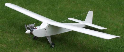
Skeyeball is an RC aircraft developed to host research and educational projects in autonomous aviation.[1] The Skeyeball Vision Project, described here, has the object of developing a tracking system that follows an object in a relatively simple (uncluttered) scene, in live video. This vision system is to be integrated into a larger robotic navigation system used to steer the semi-autonomous model airplane into holding pattern above a selected feature on the ground.
1.1 History of the vision system
The Skeyeball vision was first envisioned as a subsystem implemented on a microcontroller chip. It soon became obvious that a fast (and not too costly) implementation of the early processing stages was needed: vision became an ASIC-cum-microprocessor system, and it is still such a system today. [2]
The development has gone through two distinct phases. The first phase yielded a strictly laboratory prototype: the hardware was built from vendor prototyping boards, and the processors included a Xilinx XC4010 FPGA and a Motorola MC68332. Data were shared through an SRAM on the common bus. This architecture required considerable data copying, and the 25 MHz MC68332 processor was rather too slow for the task. Nevertheless, the system was capable of (slow) object tracking, moving a camera on a simple gimbal.
|
|
|
|
Photograph 1: Skeyeball |
|
|
|
|
|
|
|
|
|
|
|
|
|
|
Photograph 2: Camera gimbal, phase 1. |
Photograph 3: System prototype, phase 1. |
|
|
|
|
|
|
|
Photograph 4: Aerial view of a target overflight. |
|


We then obtained some realistic footage by flying the airplane with the immobile camera. The laboratory prototype was capable of detecting target features in overflight sequences, but tracking an object reliably at flight speeds was very problematic. Photograph 4 shows a typical aerial view: the plane casts its shadow next to the bright square target (a brightly colored blanket on the grass).
This first phase gave us a fairly good insight into the minimal requirements for an air-worthy system. The second (current) phase is described in this article. Two major architectural improvements are a faster microprocessor (90 MHz Motorola ColdFire) and a dual-port RAM for shared data. Elimination of one very cumbersome proto board has also made the ASIC implementation much easier.
The fundamental vision algorithm has not seen much change over time, except for the addition of the threshold calculation in the second phase (See Section 2.1) - the improvement has been the increased speed. Much greater modifications had to be made to the data flow procedures, to take advantage of the dual-port memory and better bus architecture.
An electronic 3X zoom was added in the second phase, which works by restricting the vision field to the central one-ninth, at the appropriately higher resolution.
Finally, the system was given the proper startup procedure and radio controls, and the entire circuitry was built so as to be suitable for mounting inside the airplane. Photographs 5-8 show the equipment built in the second phase: three circuit boards, the new camera gimbal and the radio-controlled power switch. Photograph 8 also shows the radio and TV links connected to the vision system.
We have tested the airworthy implementation of the vision system, both in the lab and in the air. See Section 3.1 for the account of the test flights, and Section 3.2 for the description of tracking speed measurements.
|
|
|
|
Photographs 5,6: Circuit boards and camera gimbal, phase 2. |
|
|
|
|
|
Photographs 7, 8: Tracking system and peripherals, packaged for test flight. |
|


2. Functional overview of the vision system
2.1 Vision methodology
As stated in the introduction, the objective is to build a vision system that will follow an object in a relatively simple scene, in live video. We used a two-pronged approach to object tracking, taking into account the motion of the scene and the graphic "signature" of the object.
This approach was motivated by the fact that object recognition is computationally intensive, and impossible to accomplish on a frame-by-frame basis with the available hardware. Nevertheless, the vision system must operate fast enough not to allow the object to drift out of the field of vision.
The objective is to recognize the small dark object as the target, obtain its offset from the center of the vision field, and move the camera to bring the object to the center. Obviously, the vision system must take a still frame and base its calculation on it. In the meantime, the object will change location, perhaps even drift out of the field. By the time it is calculated, the displacement vector may well be irrelevant. To address this possibility, the drift of the scene is tracked frame by frame, and the camera moves to compensate for it. The center of the field moves along with the target, and the displacement vector, when available, will still be meaningful.
|
|
|
Figure 8: Method overview |
The motion detector works by calculating what is in effect a normalized dipole moment of a pair of consecutive video frames. It cannot detect local motion within the image, only the integrated value of spatial displacements. For simple drift motion, this is an adequate algorithm, with the caveat that it is sensitive to appearance of new objects on the periphery, which it also interprets as motion. It should be said, however, that the importance of the drift compensation decreased as we used a much faster processor in the second phase of the project (see Section 1.1).
Object recognition requires several stages by which redundant and non-essential visual information is parsed out, until we are left with a selection of well-defined objects, also referred to as the features of the scene. In our case, the stages are: thresholding, edge detection, segmentation into connected components, clean-up and signature/location calculation.
Figure 10 gives a functional overview of the vision system, where the progressively thinner arrows signify the reduction in bulk of the visual information. This is the typical "funnel" of the vision problem, leading from simple computations on large volume of data to complex ones on a small volume, yielding a number or two as the result. Let us illustrate the magnitude of this reduction: At 30 frames per second, 483 lines per frame, and 644 byte-sized pixels per line, raw camera output amounts to 9.33 Mbytes/sec. At the end of the process, the vision produces a few dozen bytes every couple of frames – actual rate depends on the contents of the image.
Thresholding refers to the usual conversion of grayscale to black and white image, and the threshold itself is obtained by simple analysis of the grayscale histogram (Reference 2, sec. 9.1). Both image thresholding and the threshold calculation are performed in hardware, on the frame-by-frame basis.
Edge detection is rendered simple by the preceding thresholding step: a pixel is defined as an edge point if it is black in color, and has between 2 and 7 black neighbors.. This step is implemented in code.
Segmentation: edge points are logically grouped into connected threads or loops, and each connected component is assumed to represent a distinct feature (object) in the scene. The output is a collection of arrays, each containing the edge coordinates of one feature. We use a two-pass algorithm described by Lumia et al. [3] (Algorithm 3 in the reference). For each image line, adjacent edge points in that and the previous line are labeled as belonging to the same connected component. Since the components can have an arbitrarily complex topology, line-by-line labeling may result in assigning several labels to the same component. These labeling equivalences are resolved by means of a depth-first graph search.
To identify a target object within the scene, we used the principal second moments (also known at the moments of inertia in the mechanics of rotation of rigid bodies [4]) as the "signature" of each object. Second moments are invariant under rotations and translations, fairly easy to calculate, and work well in simple scenes.
2.2 Biological parallels
It is not entirely surprising that certain functional analogies should develop between robotic perception, such as this real-time vision system, and perception in animals. While such analogies must not be taken too literally, they provide a glimpse at useful generalizations to be made about perception problems, and we will sketch them out as appropriate. [5]
For example, camera motion based on feature recognition bears a similarity to the (involuntary) saccadic motion of the eyes, the one-shot movement that brings a detail of interest into the center of the vision field. Eyes' saccades are fast, have large amplitude (as large as the displacement of the object of interest), and they are ballistic movements, i.e. they are not corrected along the way. Such a motion is compatible with a need for speed over precision: if the object identification is computationally intensive, use the result to full extent, and as fast as possible. [6]
|
|
|
Figure 10: Architecture and data flow |
3. Project Status
3.1 Capabilities and limitations
We have tested the lab vision system by manually moving irregular shapes in a vision field fairly free of random clutter, and also by means of a rotating table (Section 3.2 below).
The recognition system tracks its target reliably under translation and rotation, and in the presence of several shapes introduced as interference. Excessive skew breaks off the tracking, since the vision algorithm makes no provision for it, but an oblique view of ca. 20 degrees is still acceptable (Section 3.2). Likewise, occlusion is interpreted as a change of shape, and the target is lost when partially occluded (e.g. by drifting beyond the edge of the vision field). These limitations are obvious consequences of the vision methodology described in Section 2.1 and Figure 10.
The tracking and motion detection work equally well with the zoom engaged. As expected, zoom makes the system more reliable in tracking small targets, at the expense of limiting the field of vision to the central one-ninth.
The tracking system has been deployed in two test flights of the Skeyeball aircraft so far. In the first of these, the pilot controlled the vehicle with verbal instructions from a ground monitor monitoring the video feed. The tracking component was activated once the target, a white blanket, came into view. This was a clumsy control arrangement and it proved difficult to coordinate the test. In addition, we experienced substantial radio interference in the radio signal, but believe this interference only affected the air-to-ground transmission, not the on-board image processing. The tracking subsystem exhibited unmistakable tracking behavior for short periods (one or two seconds at approximately 150 feet) that the pilot was able to keep the target within the sweep range of the camera gimbal. Tracking was also disrupted, evidently, by the presence of the landing gear. The second test flight suffered damage on take-off and test results were inconclusive.
Additional system development is needed for more extensive test flights. In particular, ground control of the camera gimbal will significantly simplify coordination between the pilot and system tester, as would a transfer of activation control to the observer. Enhanced air-to-ground communication would improve diagnostic data logging, as would a redundant image processing system on the ground workstation. However, both of these alternatives are compromised by EMI interference, which can be reduced but is unlikely to be eliminated entirely in this inexpensive system.
3.2 Measurements of the tracking speed
The Skeyeball airplane flies within a range of speeds and altitudes; our fixed-camera flights have ranged from 18 to 60 mph, with a typical speed of ca. 35 mph. Likewise, target-overflight altitudes have been from 60 to 320 ft. Consequently, the line of sight to the target feature changes direction relative to the body of the airplane, with certain angular velocity, and the vision system must be able to keep up with it. In the test flights, the target passed through the vision field of the fixed camera in time intervals ranging from 0.8 to 4.2 seconds, depending on the altitude and velocity of the airplane.
In order to obtain some quantitative measure of the vision's tracking abilities, we have constructed a test rig - a rotating table with features to track. The vision system locks successfully onto the (largest) presented feature and the camera turns following the rotation of the table. The rotation speed is gradually increased, until the tracking breaks off or target acquisition becomes impossible. Photograph 12 shows the experimental setup: the camera gimbal, the rotating table with two features, and the TV screen showing the camera's view.
|
|
|
Photograph 12: Laboratory set-up for the tracking-speed measurements |

Figure 12 shows the geometry of the setup. The speed of the table's motor was regulated by applying variable voltage, and the angular speed of the table was measured as the time needed for ten turns. A simple formula relates the table's angular speed, omega, to the camera's sweeping speed, theta:
d is the elevation of the camera above the table, and r is the distance of the target feature from the center of the table.
|
|
|
Figure 12: Table speed vs. the camera's sweep |
At d = 26.5 cm, and r = 10 cm, we found that the tracking was still reliable with the camera sweeping an arc at the maximum speed of: Smax = 45 degrees/second. The camera's field of vision is ca. 47 degrees high and ca. 60 degrees wide, which puts this vision system within the range of speeds required to keep up with the overflight speeds that were quoted above.
Of course, tracking speed depends on the complexity of the scene. These measurements were performed with two or three shapes, plus an intermittently visible edge of the table. The scene observed in a real flight is richer in features, but at least for grassland and trees, features tend to have low contrast and disappear below the threshold, which in turn is set to single out high-contrast targets.
3.3 Summary remarks on the perception problem
Real-time perception can be envisioned as a funnel in which the data volume is reduced, but the algorithmic complexity increases. Typically, there will be several stages with fairly different breadth/depth ratio.
This is intrinsically not a problem amenable to single-architecture processing. Of course, a speed tradeoff is in principle always possible, but engineering considerations such as power consumption and heat dissipation place a very real limit on that approach. We believe that it is better to use several processor architectures, each suitable for a different stage of the perception process. Appearance on the scene of configurable microchips makes this goal both realistic and appealing.
Robotic perception is also a problem in embedded computing. Requirements imposed by the small model airplane are a bit on the stringent side, and one can envision a much more relaxed design for an assembly line or security system. However, the need for perception is naturally the greatest in mobile robots. In such applications the vision system will always have to be compact and autonomous, because it bestows autonomy on a mobile device whose primary function is something other than carrying a vision system around.
Architecture should follow function, starting at a fairly low level. For example, data collection in this system is done with a digital camera which serializes the (initially) parallel image input. This choice was dictated by good practical reasons, but the system lost a great deal of processing power because of that serialization. Image input should have been done in parallel, which in turn would have required a specialized device and a much broader data path in the initial processing stage.
The segmentation stage is better suited for implementation on general-purpose processors because of the smaller data volume and more "sequential" algorithms. An architectural alternative may be possible here: segmentation could be attempted on a highly connected neural net circuit, trading off an exact algorithm for an approximate, but parallelizable, search procedure. Neural net searches, on the other hand, are usually slow to converge and may not improve the overall speed.
Animal vision cannot be separated from cognitive functions and motor coordination, and this must be true for robotic vision as well. How much "intelligence" is built into high-level processing of visual information depends on the ultimate objectives of Skeyeball: for example, searching for a 3D shape in a complex panorama is a problem different from that of hovering above a prominent feature on the ground.
In terms of steering and motor coordination, biological parallels are relevant. It is known that inertial motion sensors play a large role in the gaze control of mobile animals. Since the input from the motion sensors is simpler, and the processing presumably faster, this sensory pathway provides the supporting motion information much faster than can be obtained by visual processing. The airplane may very well benefit from an eventual integration of its vision and attitude/motion sensors.
Visual perception is an ill-posed problem, and examples of functioning compromises may be more valuable than exact results. A few pitfalls notwithstanding, we believe that a synthesis of computational, physiological and engineering knowledge will be necessary for the eventual development of reliable and versatile perception systems.
4. Hardware Architecture
4.1 Architectural components
Drawing 13 is an overview of the architecture of the vision system. Drawing 14 shows all the signals pertaining to the flow of data from the camera, through the processors and back to servo motors, but it omits some peripheral details.
Camera
The "eye" of the system is a small digital camera, producing grayscale (non-color) NTSC video signal. The camera is mounted on a gimbal driven by two servo motors, with a 50-degree range of motion in each direction, and is permanently focused on infinity.
Sync separator
The NTSC grayscale video signal contains three synchronization signals. These are extracted by means of video sync separator LM1881 by National Semiconductor, mounted on a prototyping board along with supporting circuitry.
A/D converter
We use Analog Devices' AD876, which is a pipelined 10-bit converter. It is mounted on the same proto board, with supporting circuitry for its reference voltages.
Sampling control
Digitization (frame-grabbing), thresholding and threshold calculation, motion detection and zoom are implemented as digital designs on a synchronous pair of Xilinx XC4010 FPGA's, running at 33.3 MHz. Start-up configuration is done with two Atmel's AT17LV config ROMs.
Object recognition
The entire object recognition is implemented as code, running on a 90 MHz Motorola MCF5307 ColdFire integrated microprocessor. We use a commercial evaluation board, SBC5307, with 8 megabytes of DRAM, start-up flash ROM, expansion bus and communication ports.
Image memory
The two processors share image data through a 32K dual-port SRAM, CY7C007AV by Cypress Semiconductor. Data access is implemented as a round-robin procedure, with the objective of speeding up high-volume data transfer in the early stages of the vision process.
Servo driver
The driver for the servo motors that move the camera is implemented on one of the two FPGA's. Motion feedback from the servos is generated by a PIC16F877 microprocessor, on the basis of servos' analog position signals.