We describe the experimental platform we are developing
for a redesigned H335 "Computer Structures" course
that will emphasize the link between high
level language execution and its realization at the ISA level. The
goals and philosophy of this course will be discussed in a separate
document.
The primary objective for our laboratory platform is to provide
a compelling ongoing design example in which to explore the ideas
presented in lecture. These ideas include the interface between
C and an instruction set architecture (ISA), execution contexts, event
and I/O handling, real time programming, and the CPU as an ISA interpreter.
I (GB) felt that a laboratory based upon
robots would provide a fun and compelling platform for student
projects - this is in line with what many other schools have done
however, I wanted to avoid a situation where topics from robotics
dominate the course (e.g. vision, path planning, motion control, etc.).
This meant that the basic application had to be easy to understand
with minimal additional material - hence the choice to focus
on line following robots.
Although the
basic function of line following can be realized with a simple
control loop; we're developing a somewhat enriched platform
that is capable of inter-robot communication and sound generation.
This enriched
platform provides the opportunity to introduce more sophisticated
systems programming topics such as event handling and DMA based
I/O.
In choosing a platform, I wanted to avoid the traditional
laboratory model in which students have an assigned time in which
to access shared lab platforms. In particular, I set as a goal
developing a platform that is sufficiently cheap for each student
to have exclusive use of one for the semester
(in practice we may have pairs of students
work together), and which is sufficiently robust that we can expect most
platforms to survive over six or more semesters.
I found that most of the available robot platforms are
either too expensive or too fragile to meet this goal.
We decided to develop our platform based
upon a toddlers toy - "Goofy Giggles" by Little Tikes.
This is an amazingly robust and inexpensive
toy which has the following basic I/O devices - a separate
three-button infrared remote
control, an infrared detector to receive commands,
a pair of motors which independently drive
the two wheels through a pair of gear boxes
(there is a third free caster), and a small
speaker. The toy is designed to be robust in the face of operator error -
the arrangement of the wheels allows the toy to rotate
within the diameter of the wheels and castor
which makes it hard to get the toy stuck,
and the design of the IR detector allows for
very imprecise aiming of the remote control. In addition, it
is designed to survive rough handling by the 6 month - 3 year
age group; for example, the gear boxes are protected by slip
clutches which prevent damage when the toy is pushed and the
motors are protected from stall currents.
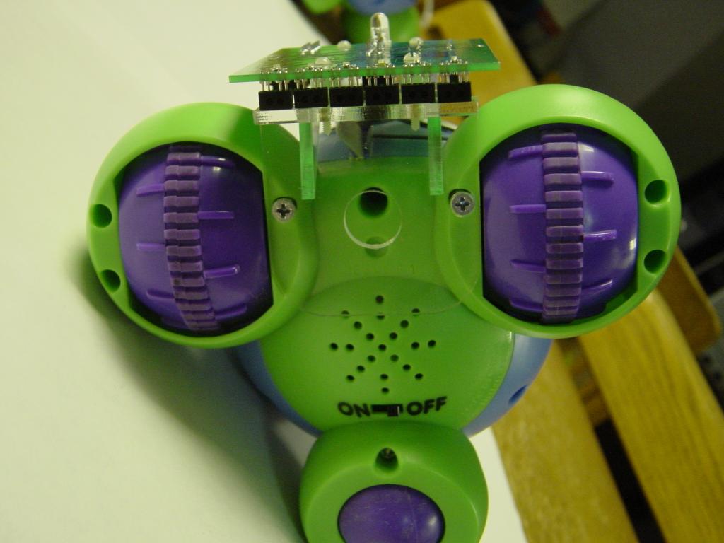
For our brain transplant, we chose to replace the internal
electronics of the toy with an external board. In addition
to providing access to all of the built-in I/O devices of the
toy, this board provides the additional sensors required to
perform line following, switches and LEDs for debugging
and preliminary experiments,an infrared emitter for
inter-robot communication, and a large serial flash memory
for storing music and data logging. The processor on this
external board is an MSP430 which we chose because it has
an ISA that meets our course objectives, it has good support
for in-circuit programming and debugging, it is supported
by a full GNU toolchain, and it has a rich set of I/O devices.
In the remainder of this document we describe Goofy Giggles and
its brain transplant in more detail.
Finally, we outline
our proposed sequence of laboratory experiments.
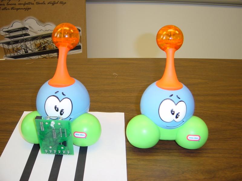
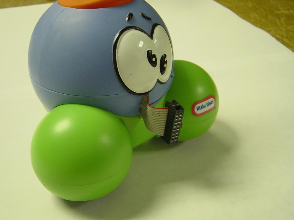
The two versions of Goofy Giggles are illustrated in the following
photograph. The modified Goofy is shown on the left on top of
a test page with three lines. As we shall show, the external circuit
board is mounted on an acrylic bracket attached to the base of Goofy Giggles
and is interfaced through a ribbon cable to the internal I/O devices.
An important component of Goofy Giggles is the IR detector which
is contained the orange ball on top; this detector has a well designed
optical system consisting of a conical mirror which makes the system
very robust in the face of mis-aiming of the control.
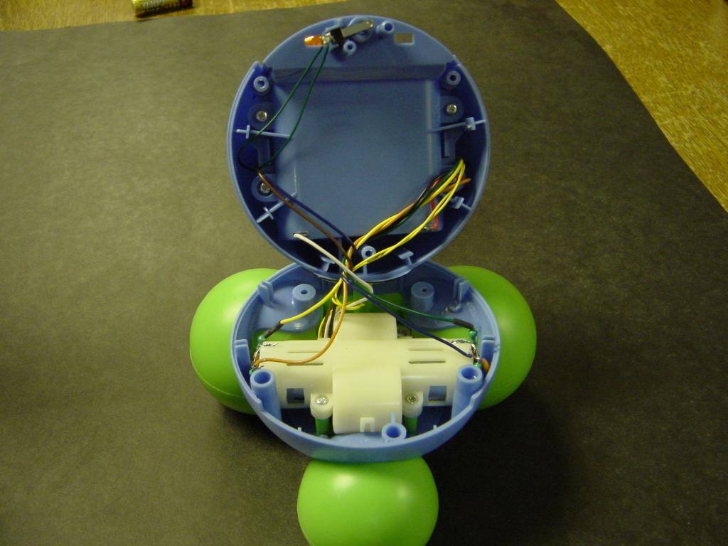
Goofy Giggles is assembled in three layers. Depending upon the screws
removed from the bottom, it is possible to access the electronics,
motors, or wheels. Our modifications require accessing only the
electronics. The motors are provided with a pair of robust gearboxes
along with current limiting resistors:
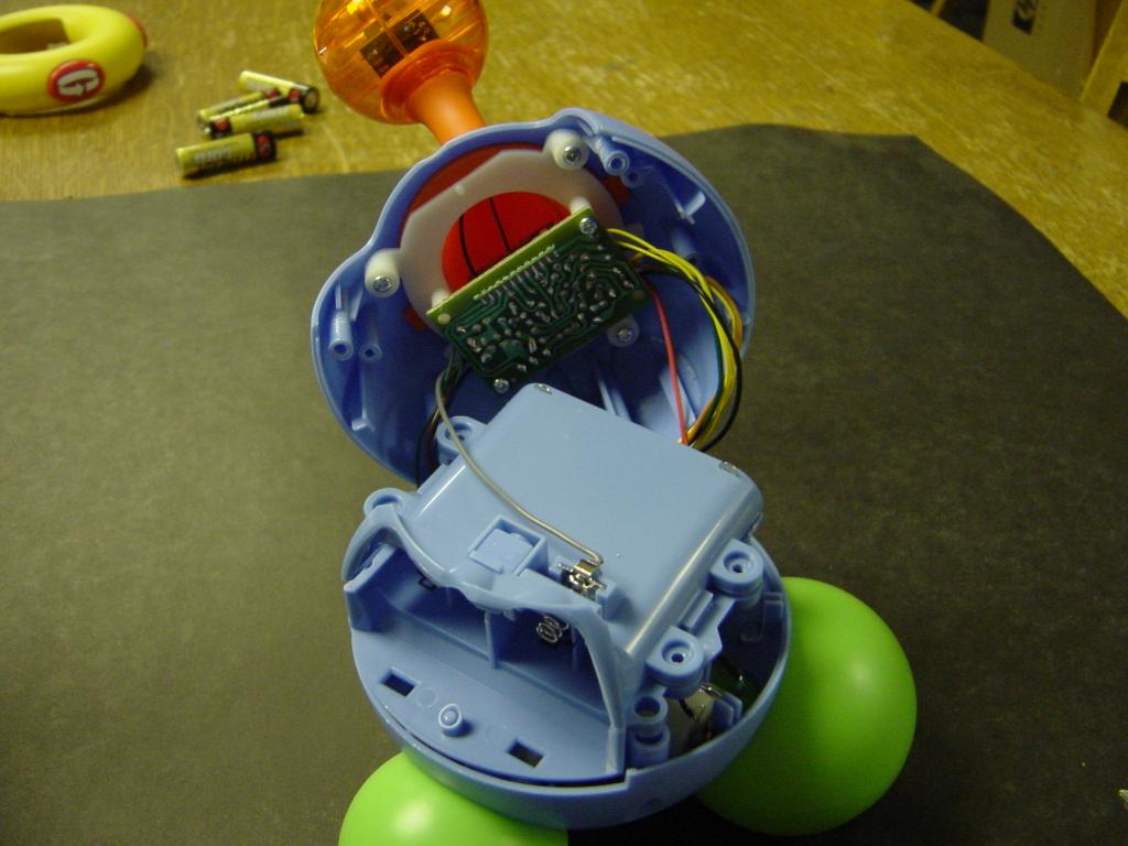
The electronics consist of a single circuit board. In the following
picture, this is visible along with the battery box which holds 4 AA
batteries.
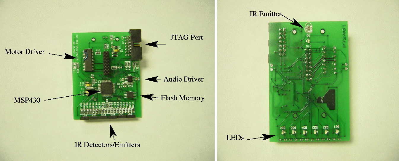
The primary circuit board for Goofy giggles is illustrated below.
The board is designed so that all components with the exception
of the IR emitter and LEDs are sandwiched between the PCB substrate
and the mounting bracket. We intend to provide a passivation layer
for the exposed portion of the board. The primary components
are the processor, audio and motor drivers, serial flash,
IR detector emitter pairs,
and the IR emitter.
The processor is an MSP430F169 which has roughly
60K flash and 2K ram. In the future a component with 10K ram will be
available in the same package; this will enable experiments involving
multiple execution threads. The audio driver provides an amplifier
which matches the output of the D/A converter (on the processor) with
the speaker of of Goofy giggles. The motor driver provides a pair of low
dropout H-bridges to enable the processor to independently control the
direction of the two motors; speed control will be through PWM.
The IR detectors/emitters form a row of six pairs which are interfaced
to the processor A/D converter. In addition, a set of six matching
LEDs are provided which can be used for visual feedback to enable the
debugging of line detection code. The serial flash memory is intended
for use as a DMA source or destination for experiments involving downloading
and playing music as well as data logging. It is interfaced the the SPI
port of the MSP430 and is supported by the DMA controller on the MSP430.
The IR emitter is provided for possible use in communication
experiments between robots.
Finally a, connector is provided to access the JTAG debugging port
of the MSP430. This conforms to the connector provided with the
TI FET tools and supported by GDB. In addition, we have used two
extra pins to provide a serial interface to a UART on the MSP430; we expect
to provide an adapter to enable the use of this serial port.
The illustrated board is our first prototype. For production we
intend to add a simple battery charger supported by a "wall wart" to
enable the use of rechargeable batteries in Goofy Giggles.
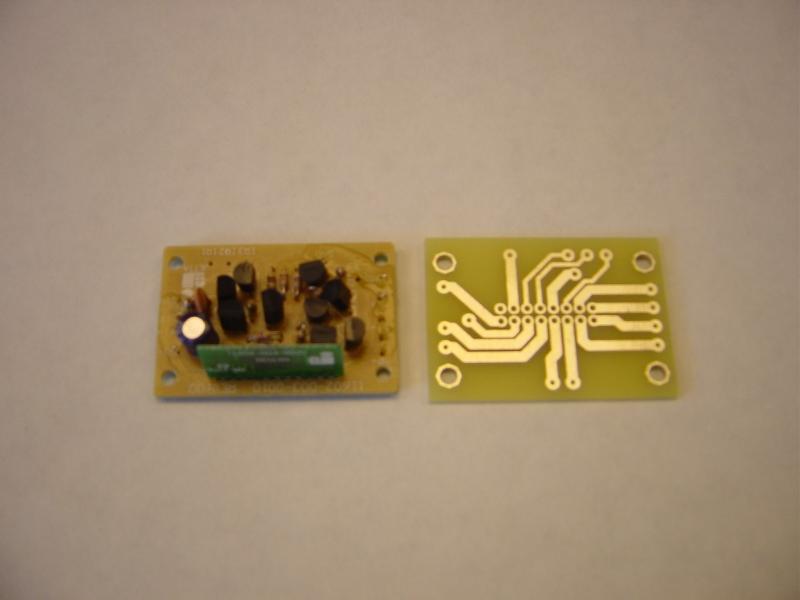
As discussed above, the "new brain" for Goofy giggles is external. We
built a small adapter board to replace the internal electronics which
connects the existing wires to a single ribbon cable. The design of this
board isn't critical; however, we chose to mimic the existing wire layout
to simplify the "transplant"; for the production version we
will add a solder mask and coded silkscreen.
The ribbon cable is routed through a slit created in Goofy Giggles face.
The ribbon cable will be keyed at both ends to ensure correct assembly.
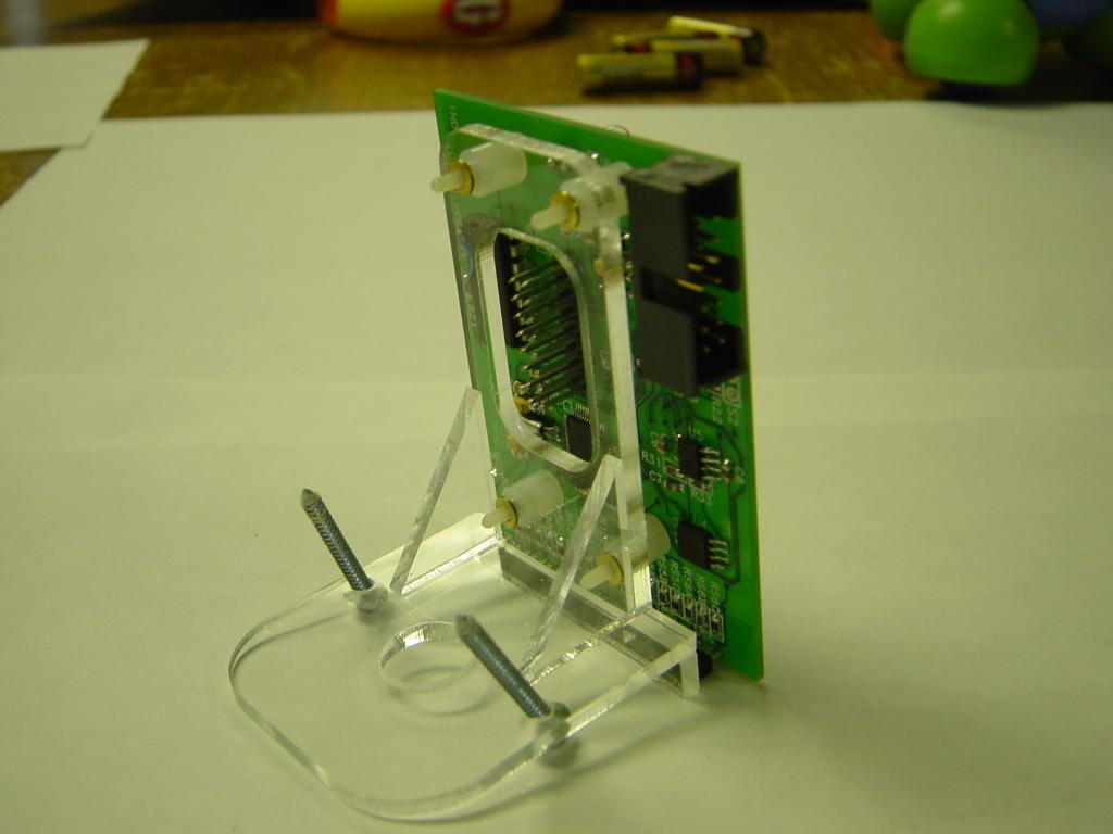
As mentioned previously, the external circuit board is mounted on
an acrylic bracket
This bracket was designed to facilitate the use of the existing
mounting screw locations on Goofy Giggles
The bracket is produced by a custom laser cutting service for approximately
$4/unit. We perform the assembly from the laser cut parts.
We are currently developing the set of laboratory experiments. We've
verified the correct operation of most aspects of our new "brain."
The proposed experiments are designed to build toward a final
project - line following - and a class time trial (with additional
points for "style"). Along the way we want to provide experiments which
illustrate various ways to architect such a software system.
The list of proposed experiments (along with the expected number of weeks) is
given below.
(2) C Tools
Emacs tutorial
gcc
gdb tutorial
make
(2) C on MSP430
Simulator: some simple programs, gdb interaction
Target: compiling for and executing on target
Buttons and Lights
Console I/O
(1) Timed programs (polling)
Sensor scanning
Playing music
Motor drive (on/off)
(1) Timed programs (interrupts)
Cyclic executive
Decoding IR
(1) Resurrecting Goofy -
Write a program to reproduce the
standard behavior of Goofy Giggles. A separate music file will be provided.
(1) C/Assembly interface
(1) External Flash
We are grateful to Little Tikes for donating the Goofy Giggles toys
required for our laboratory. In addition, we are grateful to TI
for providing many of the components.
File translated from
TEX
by
TTH,
version 3.61. On 1 Sep 2004, 08:24.